How this project started out
I can't quite remember when, but a couple of months after buying my 3D printer I was exploring Thingiverse like crazy. In a crazy crusade across Thingiverse I randomly discovered Adafruit's Mini UNTZtrument.
The gist of the project already sounded fun: making a MIDI instrument with an Arduino. But I saw other potential. At this time I was already becoming more accustomed with advanced electronics and advanced ESPHome and building my own devices using ESP8266 and 3D printing. To me this project looked more like a great fit to build my own ESP based button controller (or "macropad") much like you would see in futuristic space ship consoles: one controller to trigger a lot of actions, acting like an extension of my hand, toggling home automation flows / triggers / states like a true spaceship operator.
So I set out and started this rather long print for the enclosure...
The journey towards finding the right hardware
OK. So there were a couple of things I needed here:
A wifi connected microcontroller to interface with Home Assistant or other devices on my LAN network
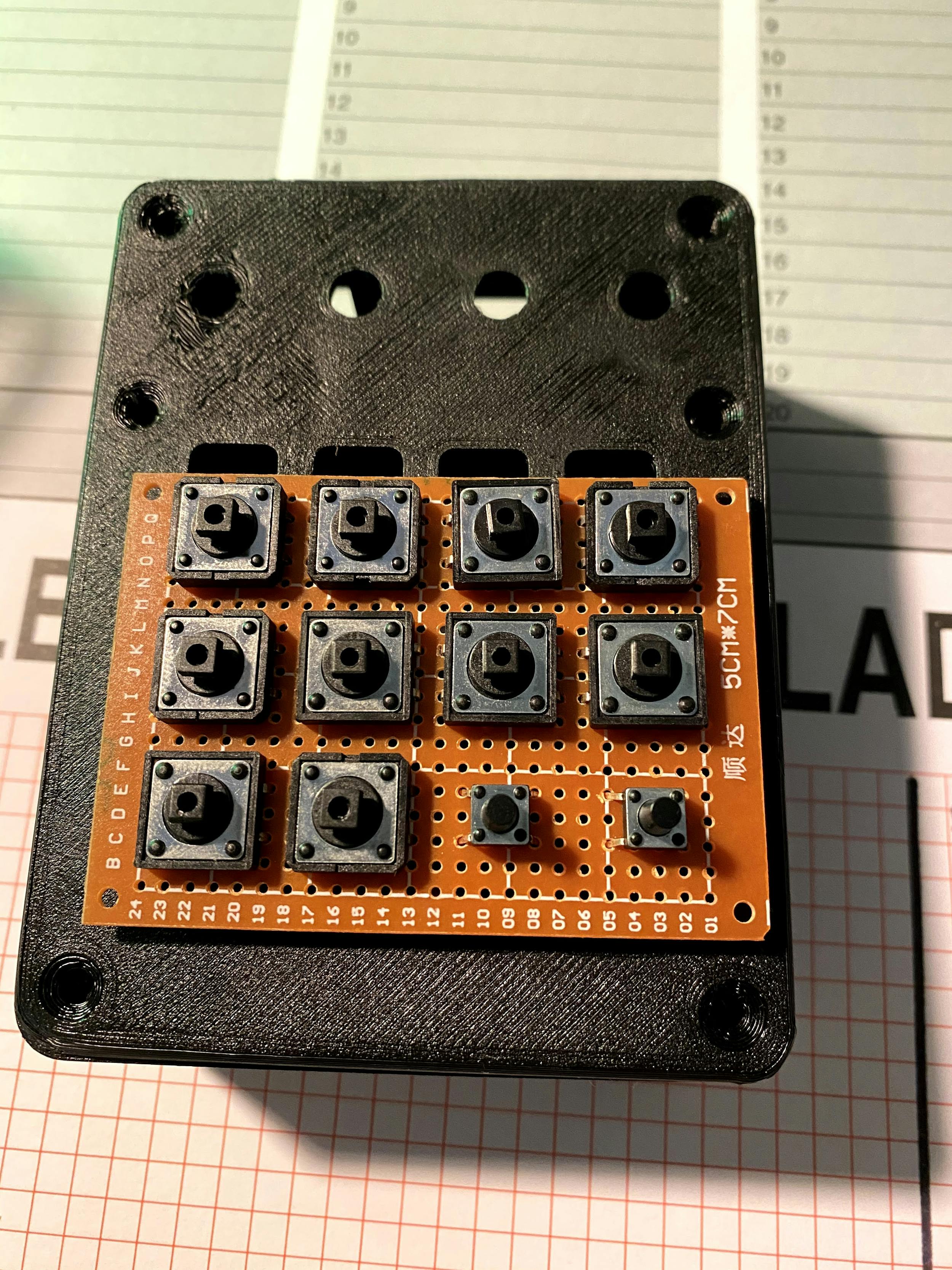
16 push buttons for the bottom part of the controller, to trigger different actions
4 components with a round shaft for the top part of the controller, options here were still open.
At that time I always hastily defaulted to an ESP8266 (Wemos D1 Mini) for anything smart home that I made myself. So with my soldering iron in hand, I set out to my desk to wire up some components on a protoboard. But the first obstacle already found its way on my path here.
How can I wire up 16 buttons to an ESP8266 that has only 11 GPIO inputs?
It took a lot of research because it was a new concept to me but there is a concept called button matrix that allows you to wire up a lot of buttons using a limited amount of pins. Curious to try this out, I started soldering buttons on protoboard with the best understanding of button matrices in the back of my head:

And I failed. It didn't work as it should, the concept baffled me and as to this day, I still kind of don't know how it works but I believe it identifies the buttons in the matrix by measuring a variable resistance that is mapped to each button.
So there it was: at this point I gave up. I could not find the joy/strenght/time anymore to continue with my controller, so the enclosure, a flaky button protoboard and ESP8266 landed in my "half-assed projects I gave up on" box.
Until, over half a year later my friends got me excited again to finish this. But this time I had much more newly acquired knowledge.
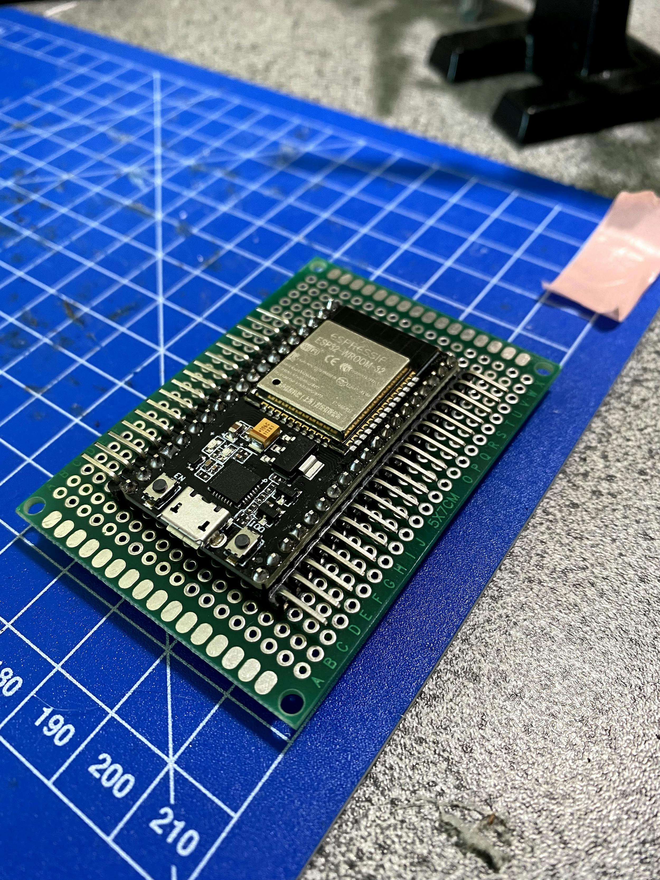
ESP32 to the rescue
My friend Toon told me about ESP32 and in an impulse shopping spree I ordered a few a couple of months back. The one thing I had remembered him saying was that ESP32 had a lot of more GPIO pins. This was my solution! All that was required was to swap my trusty ESP8266 with a greenfield ESP32. Additional benefit: I had multiple ADC pins if I wanted more analog inputs and multiple GNDs (Wemos D1 Mini only has one).
Suddenly it all made sense to me. I had long prototyping sessions, soldering nights and diagram sketching headaches but eventually landed on this bill-of-materials:
Microcontroller: NodeMCU ESP32S
Top left: Momentary latching push button
Middle left: 10K Potentiometer
Right left: Single WS2812 LED cut from a strip
Top right: Rotary encoder
16 large square push buttons
Wiring up the hardware
Connecting the inputs to the ESP32 is straight forward: there are 17 buttons to connect to digital GPIO inputs, 1 potentiometer to connect to an ADC input, 1 LED to connect to a digital GPIO input and then the rotary encoder which connects to 1 GPIO input for it's rotary movement and 1 for the press which acts as a button.
In order to keep this project somewhat modular so I could swap out the ESP32 later, I decided to add headers to the protoboard and then solder screw terminals for the VCC/GND lines required for the inputs.
Then I started to wire up GND wires for each input:

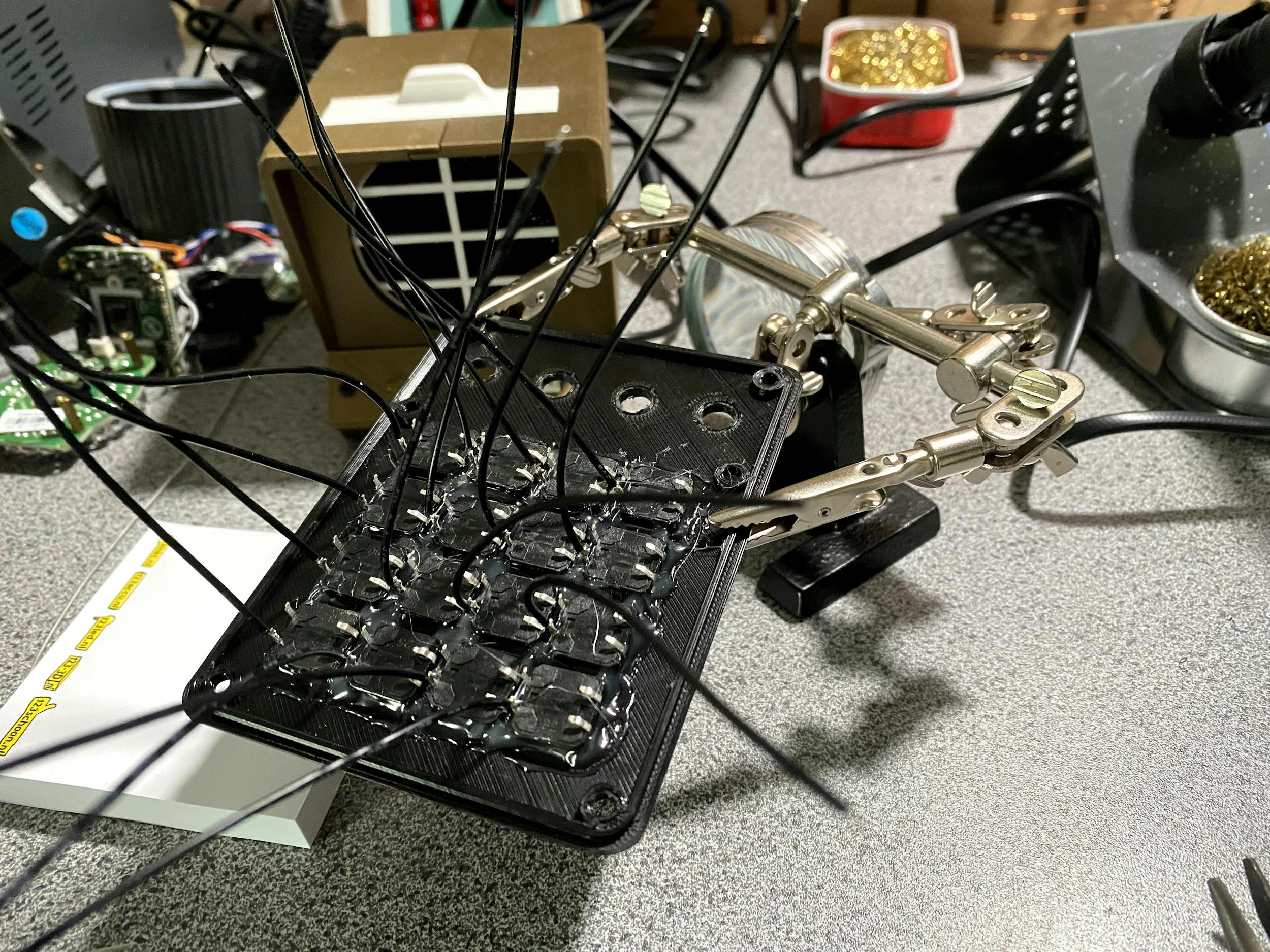
Then it was ready for its first POC by wiring up some buttons to the screw terminals and inputs to validate the button presses are being recognized by the ESP32 and my wiring was correct.
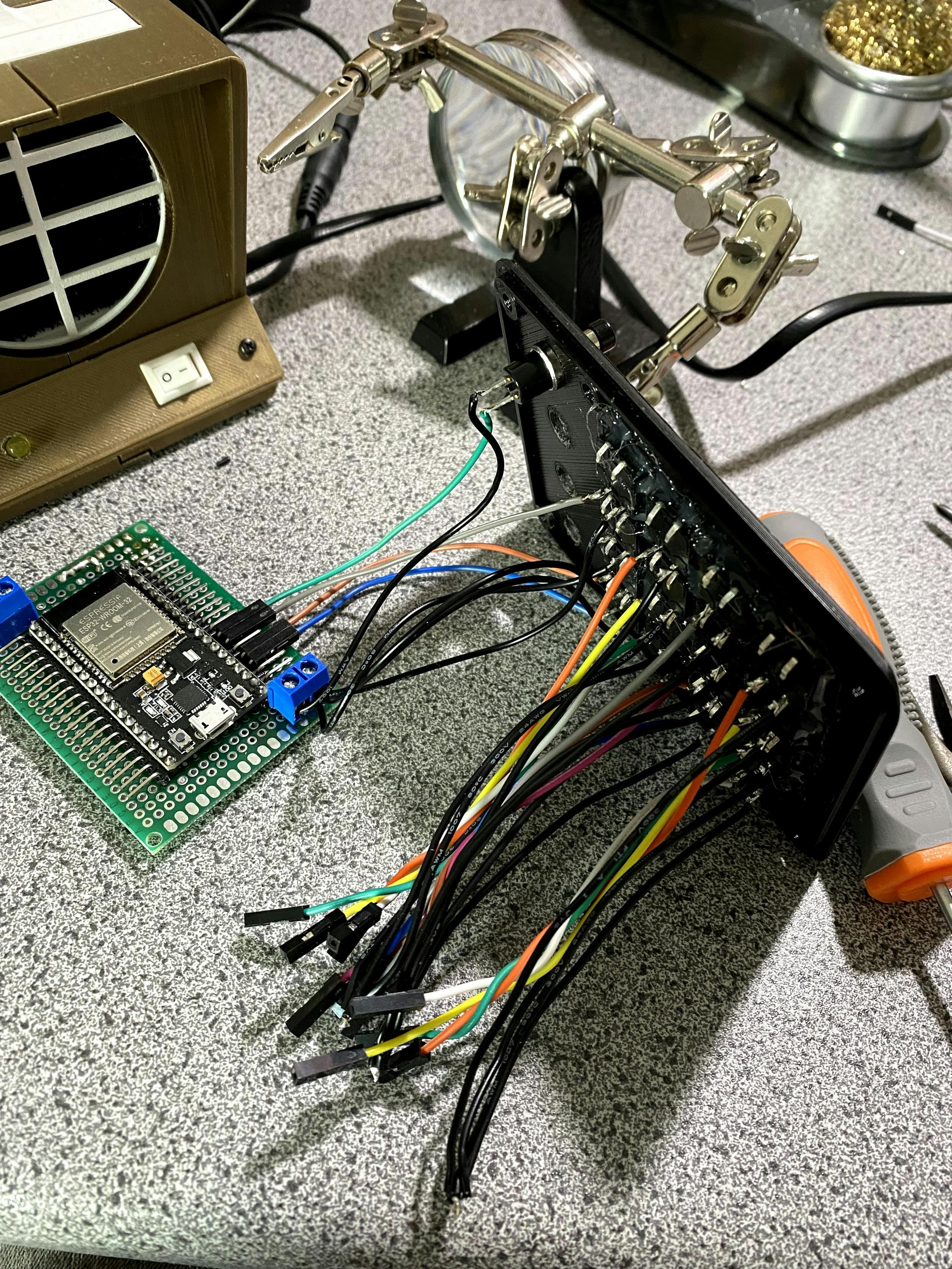
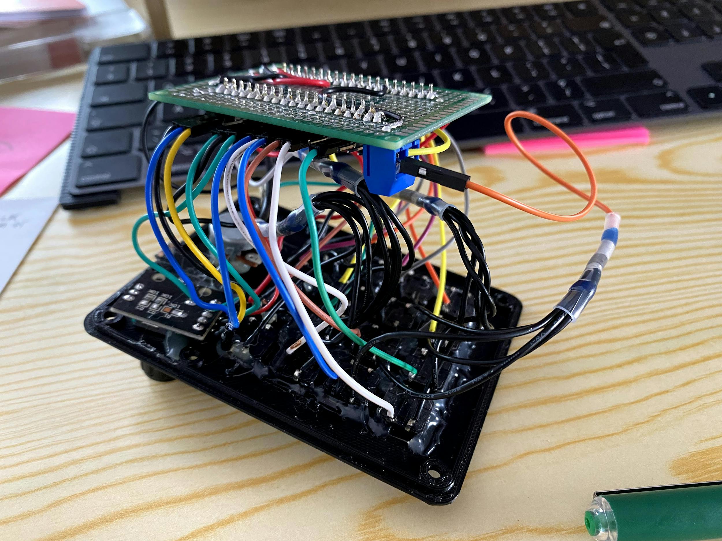
Once I verified everything was OK, I wired the whole thing up in a somewhat tedious manner. My goal here is to not open the case up unless I really need to so this wiring works fine for now. A later revision would probably have some neater wiring or wire routing.
The WS2812 LED requires 5V to function. Luckily the ESP32 (and the ESP8266) have a 5V (VIN) pin which can be used to either supply 5V to the ESP32 and power it, or in my case: pass through the 5V received from the micro USB port to other components, like the LED.
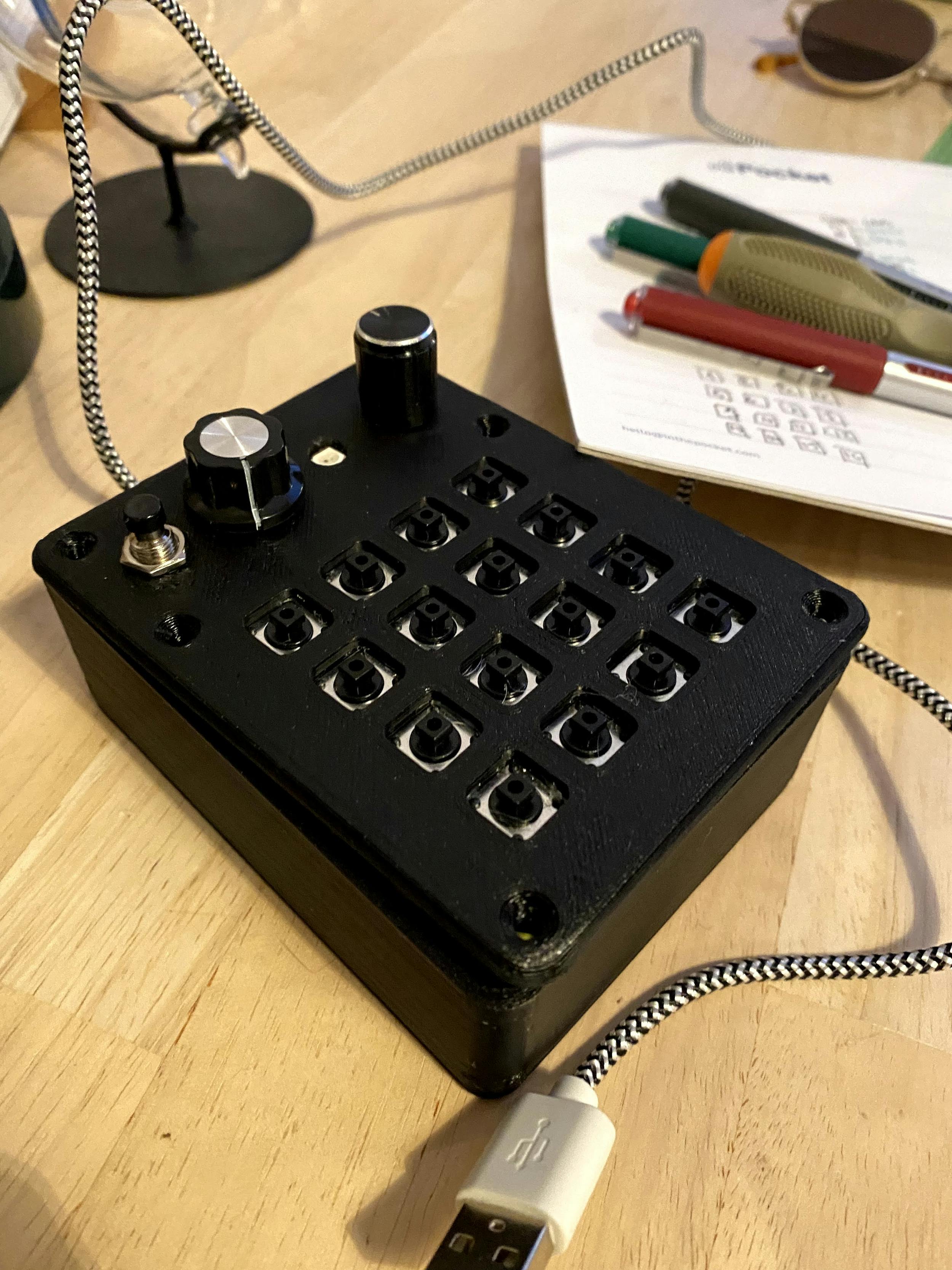
And after this: ready for enclosing it in the box. I still had some final prints to do (keycaps and a LED diffuser) but it was ready for its first real use via ESPHome and Node-RED!
Installing the correct firmware
ESPHome makes writing/configuring firmware for ESP-based MCU's dead easy. There really isn't much to write here that the ESPHome docs don't already cover.
I decided to publish each button to a esphome/${device_name}/button topic with the number ID in the payload and then follow that topic format for the rotary encoder and potentiometer. For the LED, I am not exposing this to HA, MQTT or Node-RED since I just wanted it to act as a status LED for the controller's state.
You could just copy my config below, but I suggest looking into ESPHome docs for a bit. I'm using advanced concepts like lambdas & packages here to make automations easier.
yamlsubstitutions:device_name: esp32_mqtt_button_boxfriendly_name: "ESP32 MQTT Button Box"packages:base_config: !include ../../common/base.yamlwifi: !include ../../common/wifi.yamlmqtt: !include ../../common/mqtt.yamlesphome:platform: ESP32board: nodemcu-32son_boot:then:- sensor.template.publish:id: modestate: 0- light.turn_on:id: color_ledbrightness: 0.5effect: "Breathe"red: 100%green: 100%blue: 100%- light.turn_off:id: color_led- light.turn_on:id: color_ledbrightness: 0.5red: 100%green: 100%blue: 100%ota:binary_sensor:- platform: gpioname: "${friendly_name} — Rotary Encoder Button"internal: truepin:number: GPIO21mode: INPUT_PULLUPinverted: trueon_click:min_length: 1000msmax_length: 2000msthen:- sensor.template.publish:id: modestate: !lambda |-auto call = id(color_led).turn_on();call.set_transition_length(1000);call.set_rgb(1.0, 1.0, 1.0);call.perform();return 0;on_press:- mqtt.publish:topic: "esphome/${device_name}/button"payload: "rotary_encoder"- sensor.template.publish:id: modestate: !lambda |-auto call = id(color_led).turn_on();call.set_transition_length(1000);if (id(mode).state == 0) {call.set_rgb(1.0, 1.0, 0.0);call.perform();return 1;}if (id(mode).state == 1) {call.set_rgb(1.0, 0.0, 1.0);call.perform();return 2;}if (id(mode).state == 2) {call.set_rgb(0.0, 1.0, 1.0);call.perform();return 3;}if (id(mode).state == 3) {call.set_rgb(0.5, 1.0, 0.8);call.perform();return 4;}if (id(mode).state == 4) {call.set_rgb(1.0, 1.0, 1.0);call.perform();return 0;}- platform: gpioname: "${friendly_name} — Top Button"pin:number: GPIO13mode: INPUT_PULLUPinverted: trueon_press:- mqtt.publish:topic: "esphome/${device_name}/button"payload: "top"- platform: gpioname: "${friendly_name} — Button 1"pin:number: GPIO33mode: INPUT_PULLUPinverted: trueon_press:- mqtt.publish:topic: "esphome/${device_name}/button"payload: "1"- platform: gpioname: "${friendly_name} — Button 2"pin:number: GPIO32mode: INPUT_PULLUPinverted: trueon_press:- mqtt.publish:topic: "esphome/${device_name}/button"payload: "2"- platform: gpioname: "${friendly_name} — Button 3"pin:number: GPIO14mode: INPUT_PULLUPinverted: trueon_press:- mqtt.publish:topic: "esphome/${device_name}/button"payload: "3"- platform: gpioname: "${friendly_name} — Button 4"pin:number: GPIO18mode: INPUT_PULLUPinverted: trueon_press:- mqtt.publish:topic: "esphome/${device_name}/button"payload: "4"- platform: gpioname: "${friendly_name} — Button 5"pin:number: GPIO26mode: INPUT_PULLUPinverted: trueon_press:- mqtt.publish:topic: "esphome/${device_name}/button"payload: "5"- platform: gpioname: "${friendly_name} — Button 6"pin:number: GPIO25mode: INPUT_PULLUPinverted: trueon_press:- mqtt.publish:topic: "esphome/${device_name}/button"payload: "6"- platform: gpioname: "${friendly_name} — Button 7"pin:number: GPIO15mode: INPUT_PULLUPinverted: trueon_press:- mqtt.publish:topic: "esphome/${device_name}/button"payload: "7"- platform: gpioname: "${friendly_name} — Button 8"pin:number: GPIO5mode: INPUT_PULLUPinverted: trueon_press:- mqtt.publish:topic: "esphome/${device_name}/button"payload: "8"- platform: gpioname: "${friendly_name} — Button 9"pin:number: GPIO12mode: INPUT_PULLUPinverted: trueon_press:- mqtt.publish:topic: "esphome/${device_name}/button"payload: "9"- platform: gpioname: "${friendly_name} — Button 10"pin:number: GPIO27mode: INPUT_PULLUPinverted: trueon_press:- mqtt.publish:topic: "esphome/${device_name}/button"payload: "10"- platform: gpioname: "${friendly_name} — Button 11"pin:number: GPIO16mode: INPUT_PULLUPinverted: trueon_press:- mqtt.publish:topic: "esphome/${device_name}/button"payload: "11"- platform: gpioname: "${friendly_name} — Button 12"pin:number: GPIO17mode: INPUT_PULLUPinverted: trueon_press:- mqtt.publish:topic: "esphome/${device_name}/button"payload: "12"- platform: gpioname: "${friendly_name} — Button 13"pin:number: GPIO4mode: INPUT_PULLUPinverted: trueon_press:- mqtt.publish:topic: "esphome/${device_name}/button"payload: "13"light:- platform: fastled_clocklessid: color_ledname: "${friendly_name} — Color LED"internal: truepin: GPIO19chipset: WS2811num_leds: 1rgb_order: GRBeffects:- automation:name: "Breathe"sequence:- delay: 1s- light.dim_relative:id: color_ledrelative_brightness: 50%transition_length: 4s- delay: 1s- light.dim_relative:id: color_ledrelative_brightness: -50%transition_length: 4ssensor:- platform: templatename: "${friendly_name} - Mode"id: modeicon: mdi:select-all- platform: adcname: "${friendly_name} - Potentiometer"pin: GPIO34update_interval: 10sattenuation: 11db- platform: rotary_encoderid: rot_encname: "${friendly_name} — Rotary Encoder"pin_a: GPIO23pin_b: GPIO22on_clockwise:- mqtt.publish:topic: "esphome/${device_name}/rotary_encoder/cw"payload: !lambda |-return to_string(id(rot_enc).state);on_anticlockwise:- mqtt.publish:topic: "esphome/${device_name}/rotary_encoder/ccw"payload: !lambda |-return to_string(id(rot_enc).state);
Integrating MQTT, Node-RED and the controller
Previous projects all used the native Home Assistant integration for ESPHome and that was fine for simple sensors that just exposed a value. This controller however performs a lot of interaction, with all these inputs.
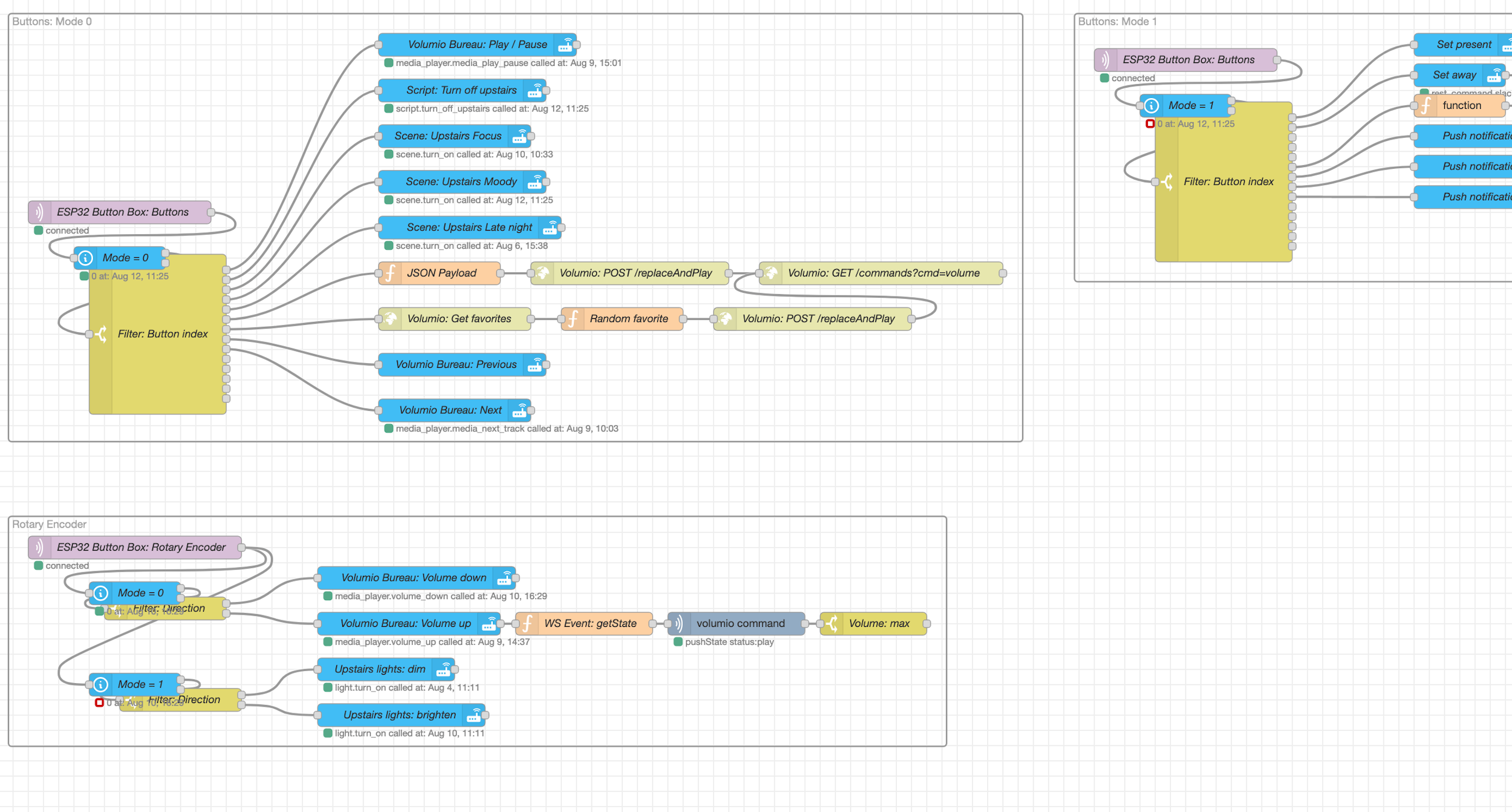
I already had Node-RED running for some other automations. To make all the different button mappings clear to me I decided the best way would be to post MQTT messages via the controller and the visualise them in Node-RED. This also makes it a lot easier to remap button functionality and keep the controller agnostic of what 'frontend' is using it.

Adding advanced features
Even 17 buttons couldn't limit me! I wanted a mode selector that would remap the buttons when under a certain mode. Pressing the first button under mode 1 (the default) for example would turn all the lights off, but then pressing that same button in a different mode could perform a different action.
The rotary encoder's button press was the most logical choice for this. Pressing it would then just iterate over the modes and keep a global reference on the ESP32 as to what mode was currently selected. Then all the buttons could use that mode. I mapped a long press on the button to reset the mode to 0.
yamlesphome:on_boot:then:- sensor.template.publish:id: modestate: 0binary_sensor:- platform: gpioname: "${friendly_name} — Rotary Encoder Button"internal: truepin:number: GPIO21mode: INPUT_PULLUPinverted: trueon_click:min_length: 1000msmax_length: 2000msthen:- sensor.template.publish:id: modestate: !lambda |-return 0;on_press:- mqtt.publish:topic: "esphome/${device_name}/button"payload: "rotary_encoder"- sensor.template.publish:id: modestate: !lambda |-if (id(mode).state == 0) {return 1;}if (id(mode).state == 1) {return 2;}if (id(mode).state == 2) {return 3;}if (id(mode).state == 3) {return 4;}if (id(mode).state == 4) {return 0;}
And then in the lambda's I could integrate this to set a different color on the LED (see the full config).
Persisting the mode was not necessary for me. Technically you could write this to the limited amount of flash memory on the ESP32, but I'd rather reset the mode to 0 when the ESP boots.
Conclusion
Tackling this project in my freetime has learned me a lot. I would do a lot of stuff differently next time I start on something like this:
Instead of wiring individual GND wires to each button, just connect all grounds of the buttons and have 1 wire for the bottom part connected to the ESP
Don't do hasty prints for something like this. Take the time to print at a higher resolution, because now removing the hot glue to move to a newly printed case is just not worth the effort
ESP32 is still limited in GPIO input, I would need to look into some sort of GPIO expander IC / addon, but for now what I have will do.
Potentiometers are really not that great of a component for projects like this, instead I would've just used 2 rotary encoders.
I would probably go for Cherry MX keys and design my own case, since keycaps for true Cherry MX macropads are more easily available and my own printed keycaps for push buttons are a bit flaky. Or buy the Adafruit Trellis.
Nevertheless I had soooo much fun creating this. I learned even more about electronics, Node-RED and home automation with this project and surely see it evolving even more in the future, maybe even for a v2 of the controller!
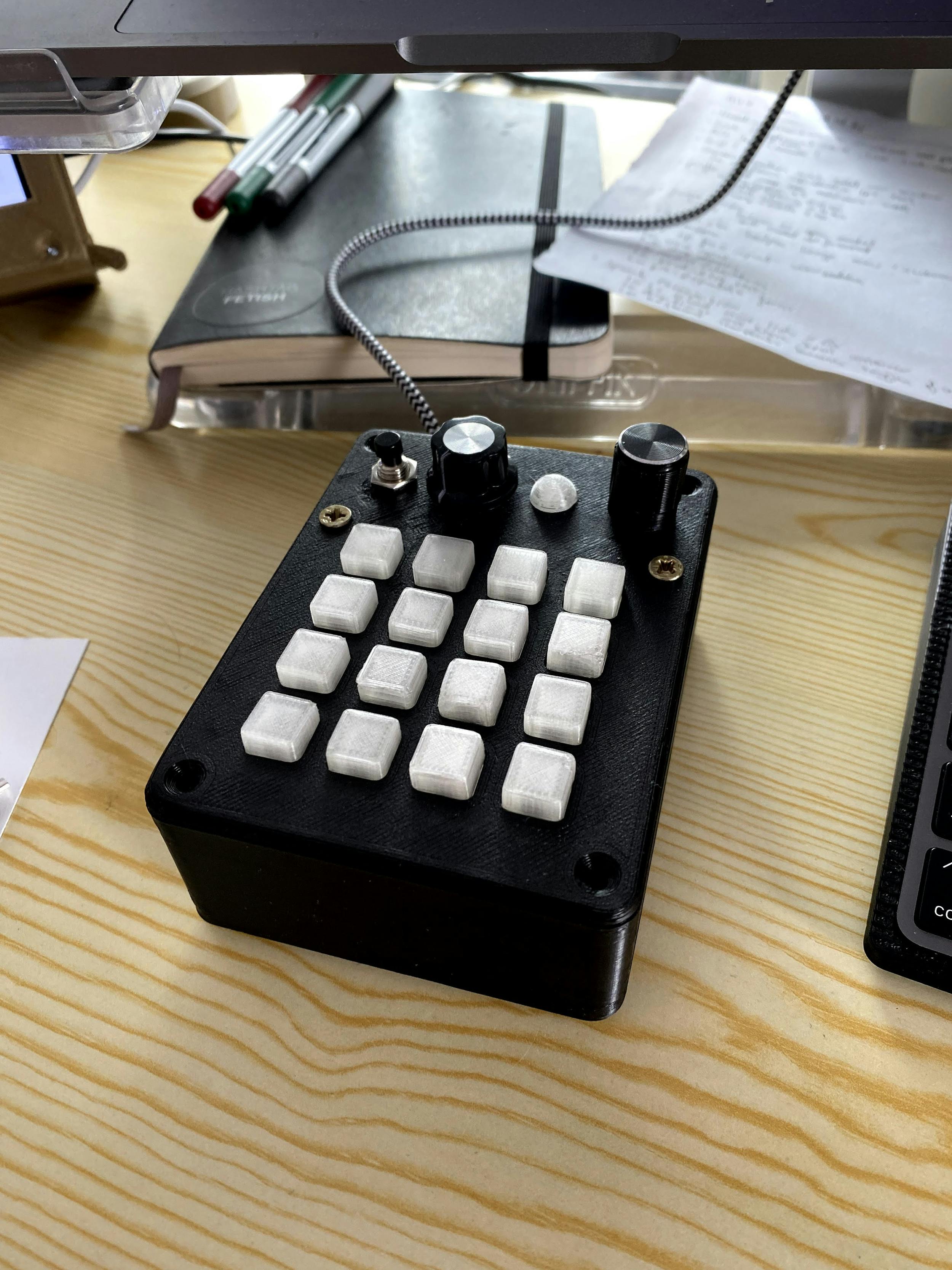
But for now this looks great on my desk: